This page is for those who might be working on their own setup and want more details.
I also did a writeup just on the pedal bushings.
I cut all of my support arms from a large scrap of aluminum which had previously been part of an unrelated assembly, so there are a few holes in my parts which are from the original metal. So if you see some holes in my photos that dont seem to belong there, it is very likely that they dont.
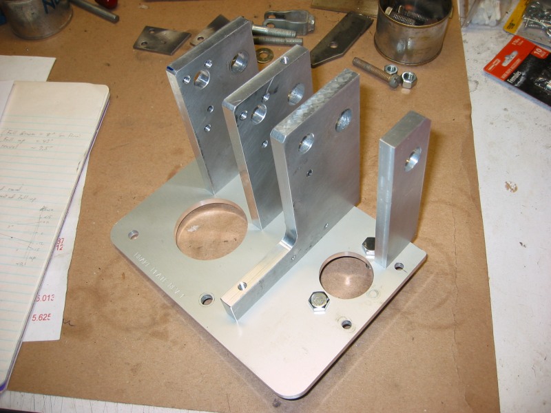
The base plate was machined by Front Panel Express. This is a company that primarily builds aluminum face plates for electronic equipment. They have a very automated process which makes full custom panels affordable. They can handle pretty much any job in flat aluminum panel up to to 10 mm thick. My base plate is 6 mm thick (roughly 1/4 inch). I could have machined this plate myself, but I am using a manual milling machine where it is easy to make a mistake, and I had done plenty enough machining already. This plate from Front Panel Express cost me less than $100, including material, is very accurately machined, and is pretty enough to use as a face plate.
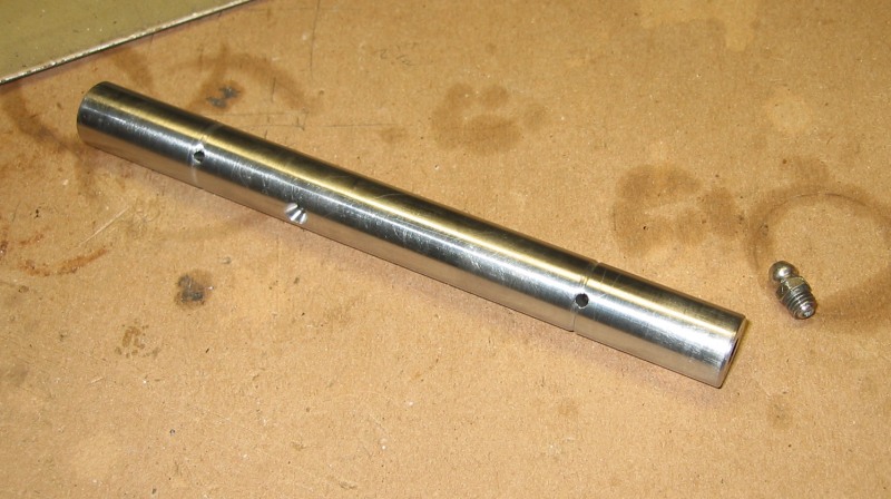
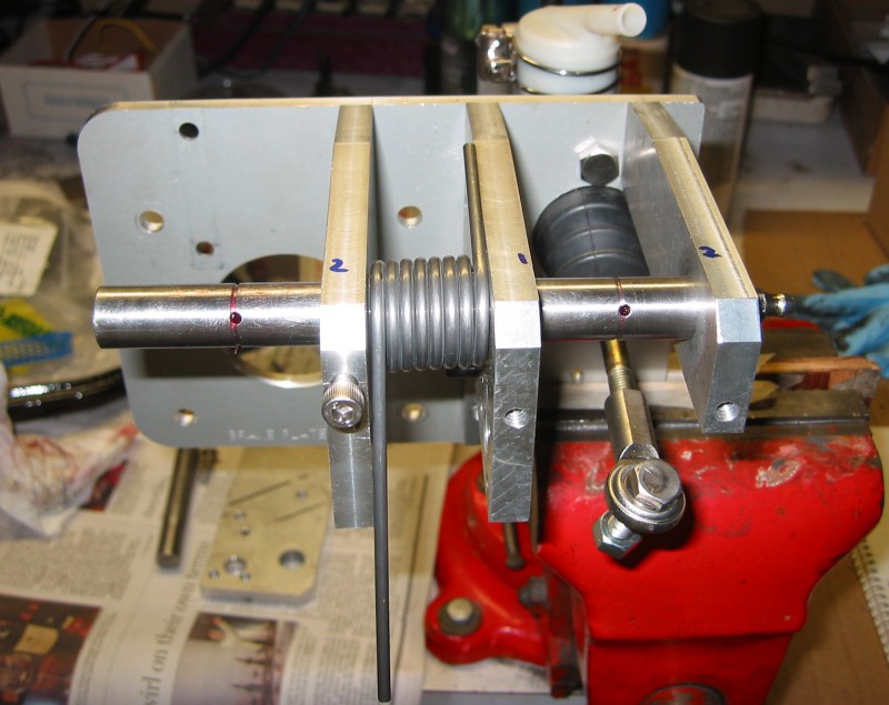
I dont have any drawings for the shaft. I center drilled this all the way through with a long 1/8 inch drill, and fitted it with a grease zert on one end. It is cross drilled and grooved under each pedal to allow grease to flow under and around each pedal bushing. This is overkill to be sure. The will probably never really be any reason to "lube" this.
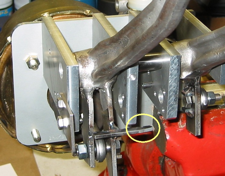
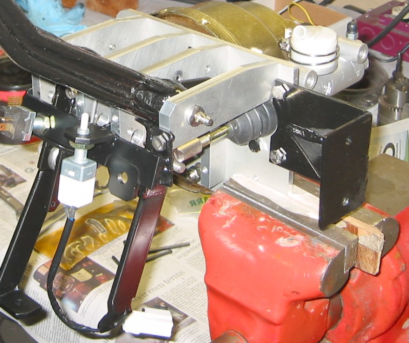
The dimple drilled into the side of this shaft is for a lock screw. This lines up with a threaded hole which is visible in the photo above, on the end of the arm, second arm from the left. The bolt that I put in that hole has a tapered end which fits into the dimple and locks the shaft into a pre-defined position.
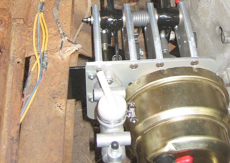
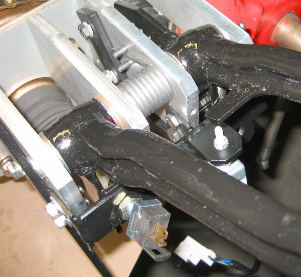
Something I totally ignored in my journals is how the brake assembly mounts to the truck. It is attached to the truck frame in three places: one bracket on the left of the base plate connecting to the frame rail, and two steel bars off of the support arms angling down and forward to a frame cross member.
It all needs to mount pretty solid. When you put your weight on the brake pedal, this is where it goes.
The two black bars sticking out in front in this photo, bolt to the frame cross member.
Here you can see part of the mounting bracket (black) between the frame and the base plate.
The length of the pedal from pivot shaft to pad is about 11.5 inches. I did a fair bit of research on the Internet trying to find "standard" pedal ratios for brake and clutch pedals. These are the numbers that I came up with:
I originally uses a 3/4 inch bore clutch cylinder, which seems to be typical in hydraulic clutch applications, but after getting it all put together I found that I couldn't disengage the clutch. It just wasn't traveling far enough. Fortunately Wilwood makes a whole line of master cylinders with a large range of bore sizes (they call some of these clutch cylinders and some brake cylinders, but there isnt really and difference other than the bore size). Search for "Combination Remote Master Cylinder" on wilwood.com. I wound up changing to a cylinder with a 7/8 bore to get the job done.
In hind sight, If I had used a clutch pedal ratio of 5:1, the 3/4 cylinder should have worked fine.
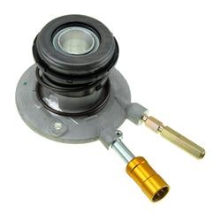
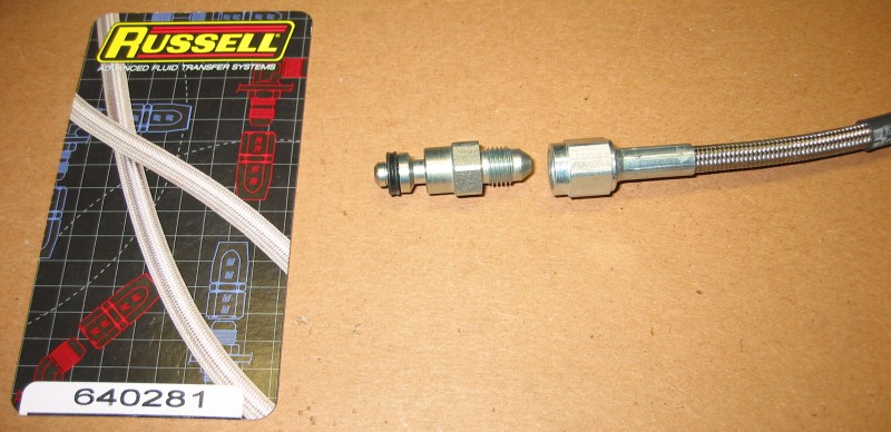
The internal clutch slave cylinders that GM uses these days have a very special quick-disconnect fitting. I have found two ways to connect to this. McLeod makes a hydraulic hose just for this (p/n 139204), with the mating fitting attached. Its a little pricey, but a nice piece.
Or you can replace the tube coming off of the slave with your own hose using this adapter from Russell (p/n 640281). This part replaces the quick-disconnect fitting and the short tube shown above, with a 3AN fitting. This part must be installed and the hydraulic line attached when you mount the slave in the transmission, because it will become completely inaccessible after the transmission is bolted up.
I do have return springs for both of the pedals. The clutch return spring can be seen here. For this, I added an extra arm off of the pedal just for the spring (at top) and a bracket off of the base plate to hold the other end of the spring (bottom). This was not particularly well thought out, the spring barely clears the push rod for the master cylinder.
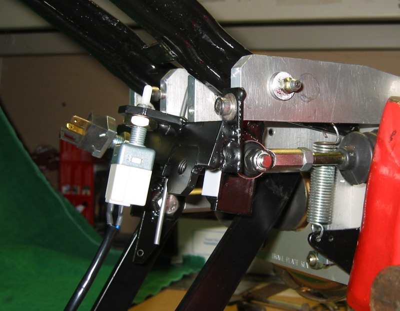
Here you can see the pedal arms. The bottom arm is for the spring, and the arm to the right is for the push rod (the small tabs around the bolt hole are to force the bolt to rotate with the pedal arm, not the rod end). I added many holes here to allow for spring adjustment. As it turned out, the farthest two holes could not be used because the spring would hit the rubber boot (see photo above), so I used the middle hole, which does not give me as much return force as I would like. But it will do for now.
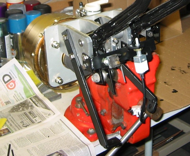
The brake return spring is shown here. This is a much stronger spring than that used for the clutch. This is a stocked McMaster-Carr spring and fits beautifully into the assembly. You can't see it, but there is a nylon sleeve under the spring, to prevent it from rubbing directly against the shaft.
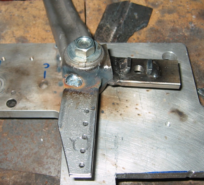
This angle shows the split pin that I used to hold one end of the spring. There are four or five of these pins in the assembly at different positions, to allow for spring tension adjustment.
The other end of the spring sticks out the bottom and sits in a small notch in an arm welded onto the brake pedal. I dont have any pictures that clearly show how the spring fits in here, but this setup works great.